

Adding Legroom to a DN Cockpit
Geoff Sobering, US 5156
Copyright 2002 Geoff Sobering - Non-commercial use allowed with attribution.
Introduction:
In the 2001-2002 season it became painfully apparent to me that my 6'3” (1.91m) body didn't fit very well into my DN cockpit. When I tried to slide down into the cockpit for the downwind legs I found my knees sticking up in an inconvenient manner. In order to get as far forward as possible, I had to press my feet flat against the forward bulkhead; this left my toes sticking up above the deck. Between my knees and toes, I had a very restricted range over which I could move the tiller (exciting when trying to round the windward mark on a windy day). In the off-season I measured my boat and investigated the DN specifications. I found that the seatback on my boat was positioned at the maximum rearward location (A.6), but the forward bulkhead was about 5 inches aft of the maximum forward position (A.7). Thus began the project to increase the legroom in my boat.
Before describing the process of relocating the bulkhead, I'd like to mention the quirkiness of the DN specifications that describe the cockpit length. The strangest part of the specifiactions is that the seatback position is measured from the steering post (A.6), while the forward bulkhead position is measured from the bow of the boat (A.7). The distance between the steering post and bow can vary between three and seven inches (A.29). Unfortunately, my boat was built with a nearly minimum length steering-post to bow distance. I gave a passing thought to scarfing an additional 3 1/2” of length onto the bow, but decided I didn't know enough about the loads on that part of the boat to feel comfortable making that modifcation. I did make a brief inquiry to the ever-helpful Paul Goodwin about the possibility of extending the bow in front of the forestay (non-structural), and found this was not allowed. Certainly, I'll build my next boat with a maximum length bow, and truly maximum length cockpit.
Construction:
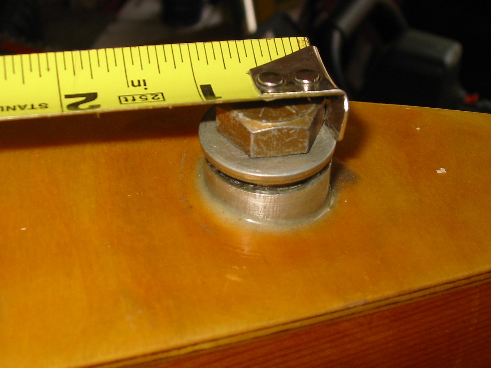
The first step was to determine a line perpendicular to the hull centerline. I did this by measuring the same distance from the steering post to either side of the hull near (but forward of) the new bulkhead position:
Since I hadn't built this boat, the next step was to non-destructively investigate the internal structure between the bulkhead and the tiller post. I used a standard ultrasonic “Stud Finder”. By sliding it across the deck, I was able to map the approximate positions of the reenforcement pieces underneath:

The point of this exercise was to find a clear spot to drill the first inspection hole:

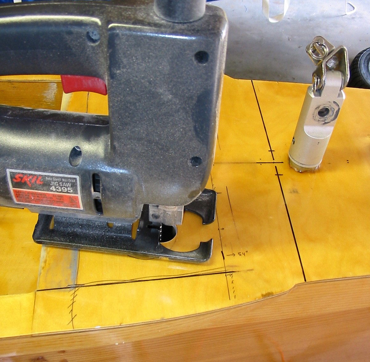
After feeling around through the hole to make sure there weren't any unexpected items inside, a jigsaw was used to cut out most of the deck (to about 1/2" of the final line):

Next, the bulk of the old bulkhead was cut out using a coping saw. A variety of tools (a bare hacksaw blade, carbide burr, and beltsander, among others) were used to remove the remaining sections of bulkhead until it nearly flush with the sides and bottom of the hull:

The removal of the final portion of the old bulkhead was done using a random-orbit sander. Tape was applied on either side of the bulkhead position to protect the sides. When the bulkhead was uniformly sanded down to the thickness of the tape, it was removed. The final sanding was done by carefully holding the sander parallel to the sides until there was no remaining bump where the old bulkhead had been:

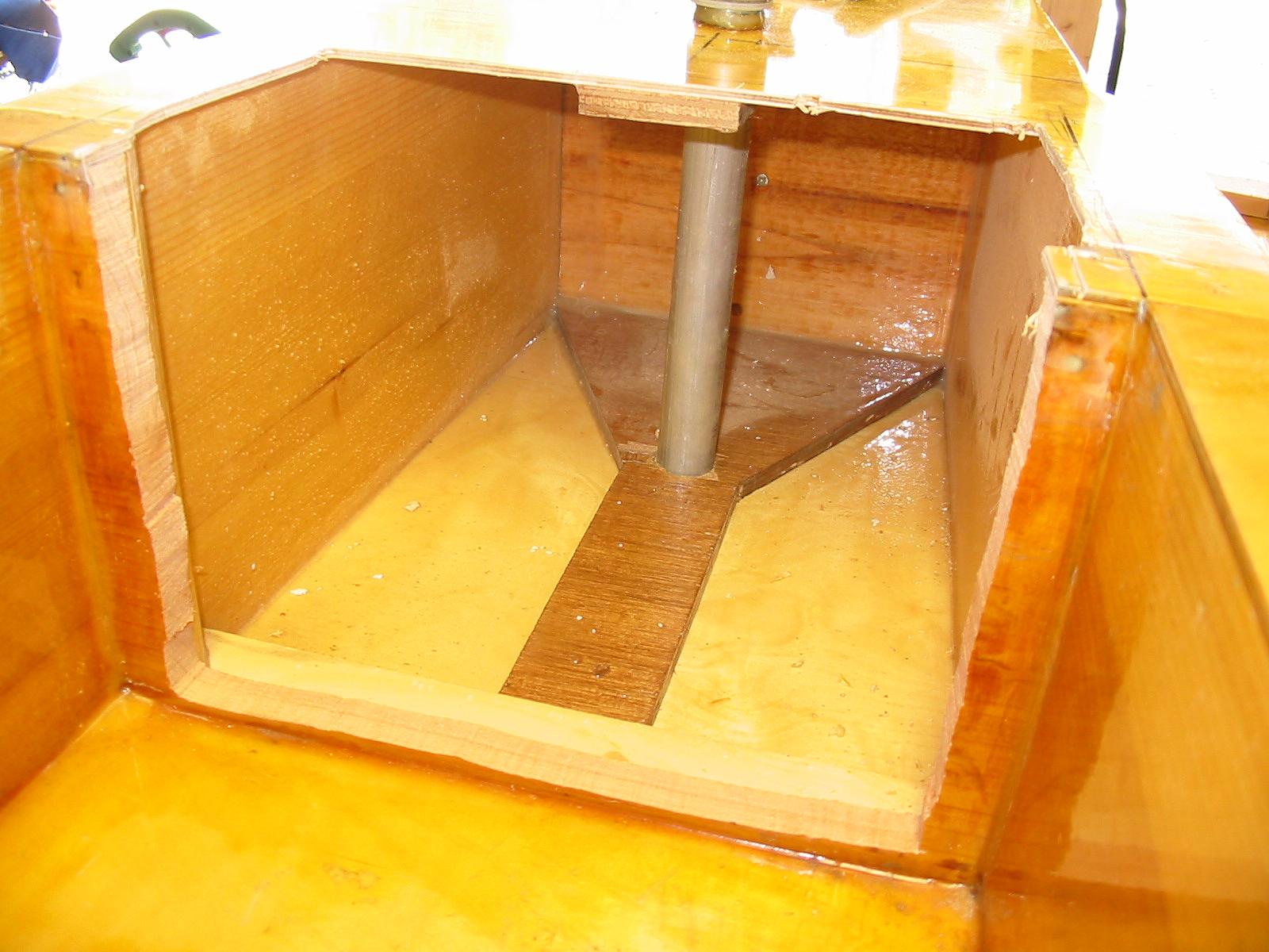
Once the old bulkhead was completely removed, the deck was carefully marked and cut at the exact postion of the new bulkhead with a saber saw and a high-quality wood blade. The newly exposed sides were sanded to remove bumps and imperfections in the epoxy surface that was previously hidden behind the bulkhead. The piece of 3/8" Occume plywood reenforcing the deck was carefully cut back the thickness of the new bulkhead using a hand-held Dremel® tool with a small (ca. 1/8" dia) straight bit. A piece of Sitka was cut to about 1/8" larger than the inside dimensions of the new bulkhead position. The new bulkhead was carefully shaped to the opening by test fitting and adjusting all four sides with a stationary belt-sander. To facilitate the final fitting, a drywall screw was screwed into the center of the bulkhead and used as a handle. The Occume plywood reenforcing the bottom skin was left in place and a notch cut in the new bulkhead.
Before gluing the new bulkhead in place, the bond between the Occume plywood renforcing on the upper and lower skins was examined. Some gaps were found and filled with thickened epoxy injected using a syringe and needle. Additionally, fillets of thickened epoxy were added on the edges of the Occume and around the tiller bearing tube.
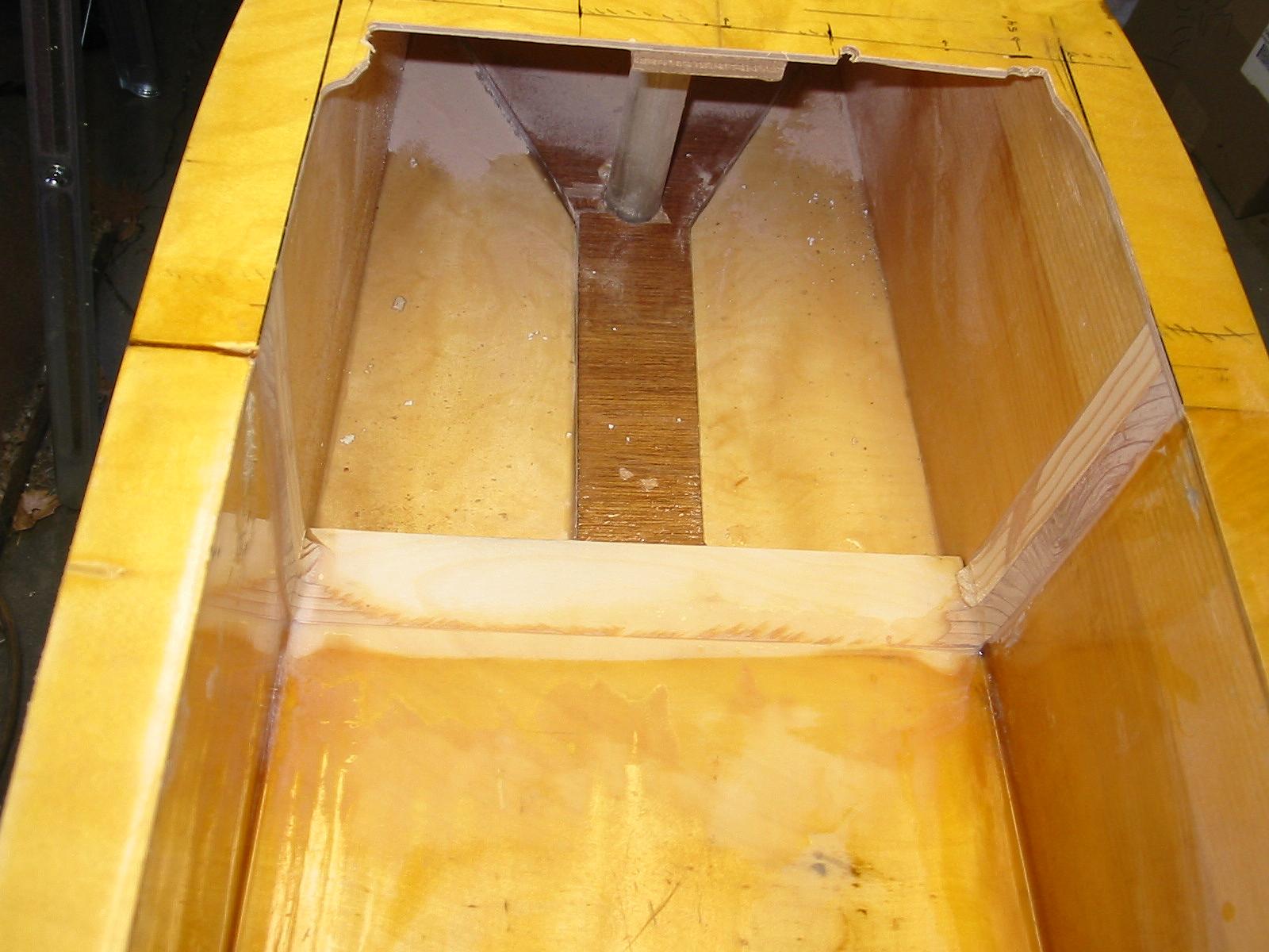
Because the forward side of the bulkhead/side-panel joint would have to be made blind (and thus couldn't be filleted with thickened epoxy), a triangular cross-section strip of wood was attached to each side of the bulkhead to increase the gluing area. A small brad was used to hold the blocking-strip in place while glue was applied to the bulkhead and the bulkhead placed in position. Excess micro-fiber (WEST ® 403) thickened epoxy was applied to the sides of the bulkhead and the blocking to help fill any gaps that might occur on the inside of the joint. The fit between the bulkhead and the existing structure was tight enough that no clamping was required to hold the bulkhead in place while the epoxy cured.
After the epoxy cured, fillets of thickened epoxy (WEST ® 404 and colloidal Silica) were added on the side and bottom joints of the bulkhead to complete the bonding:

The new section of cockpit floor as made from a piece of nominally 1/8" (actual 0.090") thick Baltic Birch plywood. A support frame of 5/8" square Balsa (purchased from a hobby-shop) was created to support the new section of floor, and the plywood was dry-fit into place:


All the pieces were coated with epoxy and bonded in place using WEST 410 MicrolightTM as the filler, since the loads in this area are minimal. The entire area was covered with wax paper and clamped by placing wieights on a piece of flat plywood that spanned the joint between the old and new floor sections. The weights were located mostly over the old floor section to try and form a flat, smooth transition. After curing, the waxpaper was removed and all the surfaces sanded smooth. Thickened epoxy fillets were added along the bottom three edges to eliminate any possiblity places for water to collect and a thin coat of neat epoxy was applied to ensured complete encapsulation of all wood. Two coats of spar-varnish (Z-Spar 1015) were applied (light sanding before and between coats):

The final step was to cut-down and reattach the vinyl and Aluminum spike protector:
